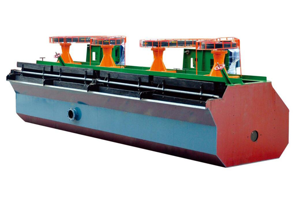
SF type floater machine is a mechanic mixing floater with double functions of self-absorption of air and slurry. It adopts forward-leaning tank and double-blade turbine of a new structure, coordinated with fluid duct and the false bottom device. The tank slurry has a double cycle of both above and below in a fixed flow manner, which contributes to the coarse mineral suspension. SF type floater is mainly composed of tank body, main drafts with impellers, motor, scraper and driving equipment. Those with a volume over 10m^3 are set with fluid duct and false bottom.
Working Principle
When SF type flotation machine is at work, the motor drives the main shaft through V belt to make the lower part of the impeller rotate. The main characteristics of this floater are demonstrated in the impeller. The impeller has a back-inclined double-sided blade, which can realize the double cycle of tank slurry. When the impeller rotates, driven by the upper and lower blades (i.e. main and auxiliary blades), the slurry in the upper and lower blade cavities generates centrifugal force and is thrown around to make the impeller cavity form a zone of negative pressure. At the same time, ore slurry on the upper part of the cover plate is sucked into the impeller cavity through the circular hole, forming an upper slurry circulation. However, the slurry thrown out of the impeller cavity is much greater than the three-phase mixture proportion thrown out by the upper blade and the centrifugal force is thus greater and velocity attenuation is slower. Moreover, it produces additional driving force to the three-phase mixture thrown out by the upper blade to increase its centrifugal force so as to improve the vacuum degree of the impeller cavity, which plays an auxiliary suction effect. When the lower blade throws out slurry around, its lower slurry will gather in the center, thus forming a lower cycle of slurry. The air is sucked into the upper impeller cavity through the suction pipe and the center cylinder to mix with the sucked slurry and form a large number of small foams. After the flow is stabilized through the cover plate, it is uniformly dispersed in the tank, forming mineralized foams. Mineralized foams float up to the foam layer, which form the foam products through the scraper.
Use
This series of floater is suitable for the selection of dark and ferrous metals,which can also be used for non-metals,such as the selection of coal and talc.
Equipment Characteristics
1. Great inspiratory capacity and low power consumption.
2. Every tank boasts the three functions of air suction, slurry suction and flotation separation to form a flotation circuit. No auxiliary equipment is needed, and a horizontal configuration is favorable for the change of flow.
3. Ore slurry circulation is rational, which could reduce coarse sand precipitation to the greatest extent.
4. It is set with the self-controlling device of ore slurry level, with a convenient adjustment.
5. The impeller has backward upper and lower blades. The upper blade produces the upper cycle of slurry and the lower cycle produces the lower cycle of slurry.
6. SF type flotation machine could be coordinated with JJF type floater to form a combined unit, in which SF type flotation machine acts as suction type and JJF type the direct current tank. The whole unit is installed horizontally.
Main Technical Parameters
|
|
| (kw) |
| 刮 |
|
| ||
Used for mixing | Used for scraper | ||||||||
Type | Effective volume | Tank size length x width x height | Processing capacity | Blade rotation speed | Scraper rotation speed | Suction amount | Weight per tank | ||
M3 | m x m x m | M3/min | kw | kw | r/min | r/min | M3/m2 min | kg | |
SF-0.15 | 0.15 | 0.5×0.5×0.6 | 0.06~0.18 | Y100L-6 | Y80L-4 | 536 | 16 | 1 | 269 |
SF-0.37 | 0.37 | 0.7×0.7×0.75 | 0.2~0.4 | Y90L-4 | Y80L-4 | 383~473 | 17 | 0.8~1 | 468 |
SF-1.2 | 1.2 | 1.1×1.1×1.1 | 0.6~1.6 | Y132M2-6 | Y90S-4 | 312 | 16 | 1 | 1373 |
SF-2.8 | 2.8 | 1.7×1.6×1.15 | 1.5~3.5 | Y180L-8 | Y100L-6 | 268 | 16 | 1 | 2138 |
SF-4 | 4 | 1.85×2.05×1.2 | 2~4 | Y200L-8 | Y100L-6 | 220 | 16 | 1 | 2582 |
SF-8 | 8 | 2.2×2.9×1.4 | 4~8 | Y250M-8 | Y100L-6 | 191 | 16 | 1 | 4129 |
SF-10 | 10 | 2.2×2.9×1.7 | 5~10 | Y250M-8 | Y100L-6 | 191 | 16 | 1 | 4486 |
SF-16 | 16 | 2.85×3.8×1.7 | 5~16 | Y280M-8 | Y100L-6 | 191 | 16 | 1 | 8320 |
SF-20 | 20 | 2.85×3.8×2 | 5~20 | Y280M-8 | Y100L-6 | 191 | 16 | 1 | 9828 |